IMAGE HANDLING
SCANNING IMAGES:
Document Scanning or Image Scanning is the action or process of converting text and graphic paper documents, photographic film, photographic paper or other files to digital images. This "analog" to "digital" conversion process (A<D) is required for computer users to be able to view electronic files.
ADDING TEXT TO AN IMAGE:
One of the most frequently asked questions by new webmasters is how to add text to their images. I have good news for everyone. It's easy, so relax.
First though you need to have a basic understanding of the graphics software you are using. The best way to learn your software is to use it and consult the help section located within it often. Sadly though most software packages do not come with printed manuals anymore. I am the type of person who likes to read a step-by-step tutorial on paper while I have my hands on the keyboard, mouse or graphics pen. I dislike having to flip back and forth between screens just to re-read instructions for the second or third time. But that's the progress of technology, right? A paperless system is what they call it.
If you are like me, simply print the tutorial or sections of your software's help manual that you know you will refer to often. Punch holes into the pages and place it into a 3-ring binder for future reference. Incidently, you can also print any article on this site in a printer friendly format by clicking on the "Printer Friendly Page" link at the top of every article page.
This mini-tutorial covers the generic steps for the three graphics software packages we recommend: Adobe PhotoShop, Jasc Paint Shop Pro and Ulead PhotoImpact.
Important: BEFORE you begin, be sure to have a backup copy of all graphics you are about to change. This will save you tons of time if something does not go right and you need to start all over again.
Open your graphics software and go to File > Open. Browse your hard drive for the graphics file you wish to apply the text.
1. INCREASING COLOR DEPTH:
If the image is a GIF, you will need to convert it or increase the color depth to 24-bit (also called True Color, 16 Million Colors or RGB).
Photoshop 5.5:
Image > Mode > RGB Color
Paint Shop Pro 7:
Colors > Increase Color Depth > 16 Million Colors (24 bit)
PhotoImpact 7:
Format > Data Type > RGB True Color
2. ADD TEXT TO IMAGE:
PHOTOSHOP 5.5:
Select the Type Tool icon (T) from the tool pallet. Place your mouse cursor on the image in the location where you want the text applied. A "Type Tool" window will popup. You can type your text within the box area, change your font face, style, size, and color. Click OK.
PAINT SHOP PRO 7:
Select the Text Tool icon (A) from the tool pallet. Place your mouse cursor on the image in the location where you want the text applied. A "Type Entry" window will popup. You can type your text within the box area, change your font face, style, size and color. Click OK.
PHOTOIMPACT 7:
Select the Type Tool icon (T) from the tool pallet. Place your mouse cursor on the image in the location where you want the text applied. A "Type Entry Box" window will popup. You can type your text within the box area, change your font facet, style, size and color. Click OK.
3. SAVE YOUR NEW IMAGE
After you are satisfied with your revised image, you need to save it. If you are working with one of our templates, we advise saving it in the same location and with the same file name as the original image located in most cases within the "images" directory.
File > Save As > Browse your hard drive for the graphics file you wish to replace or find a new location on your system. Make a note as to where you saved it if you opt to save it in a new location on your system.
DESIGNING ICONS
Icon design is the process of designing a graphic symbol that represents a program, function, data or collection of data on a computer system.
Because icons usually have a maximum size of 128 by 128 pixels, the challenge of icon design is to create an image of that size, which can reduce down to 12 by 12 pixels, that accurately portrays what the icon represents. Common examples of this are installer icons, which usually contain images of product installation media and a computer, thus showing the rough idea of installation, or icons that involve the Internet containing a globe, now the almost universally recognized symbol for the Internet.
One of the early professional icon designers was Susan Kare, who designed many of the icons contained within the original Mac OS.
Icons typically represent containers, documents, network objects, or other data that users can open or manipulate within an application. An icon usually appears with identifying text.
Sizes for icons vary from platform to platform. Two common sizes are 16 x 16 pixels and 32 x 32 pixels. In the Java look and feel, the smaller size is used in the title bar of windows (to identify the contents of the window or minimized window) and inside tree components (for container and leaf nodes). You can use 32 x 32 icons for the desktop representation of Microsoft Windows applications and for components in applications designed for users with visual impairments, or for objects in a diagram, such as a network topology.
Design icons to identify clearly the objects or concepts they represent. Keep the drawing style symbolic, as opposed to photo-realistic. Too much detail can make it more difficult for users to recognize what the icon represents.
When designing large and small icons that represent the same object, make sure that they have similar shape, color, and detail.
Specify tool tips for each icon so that assistive technologies can use the accessibleDescription property to find out how to use the icon.
Specify the accessibleName property for each icon so that assistive technologies can find out what the icon is.
Consider providing an option that enables users to switch from smaller to larger icons.
Since sizes of icons vary across platforms, determine the size requirements of your target platform and provide suitably sized icons.
Icons can appear as flat drawings or as perspective drawings. The flush 3D style is a unique effect that can be applied to either flat (2D) or perspective (3D) icons.
The following figure shows flush 3D icons for files and folders drawn in the perspective and flat styles. Icons drawn in the flush 3D style fit best with the Java look and feel. For information on how to create the flush 3D style, see Drawing Icons and Producing the Flush 3D Effect. Three visual elements appear in the sample icons: an interior highlight (to preserve the flush style used throughout the Java look and feel), a pattern to minimize dithering (described in Working With Available Colors), and a dark border.
TWO FAMILIES OF FLUSH 3D ICONS
Use a single style to create a "family" of icons that utilize common visual elements to reflect similar concepts, roles, and identity. Icons in families might use a similar palette, size, and style.
Don't mix two- and three-dimensional styles in the same icon family.
Use the flush 3D style so that your icons suit the Java look and feel.
For more on the flush 3D style, see Producing the Flush 3D Effect.
Because icons must appear on various backgrounds across platforms, the borders of graphics must maintain consistent color. Changing the appearance of an object's border to look smoother at screen resolution in relationship to a specific color is called anti-aliasing.
In most application development cases, anti-aliasing is not desirable because you are unlikely to be sure what background color the object will appear against. However, within an icon, anti-aliasing can provide smoother interior lines.
For satisfactory display on a wide range of background colors and textures, use a clear, dark exterior border and ensure that there is no anti-aliasing or other detail around the perimeter of the graphic.
DRAWING ICONS :
The following section uses a simple folder as an example of how to draw an icon. Before you start, decide on a general design for the object. In this example, a hanging file folder is used to represent a directory. | |
1. DRAW A BASIC OUTLINE SHAPE FIRST. Icons can use as much of the available space as possible because they are displayed without borders. Icons should usually be centered horizontally in the availabespace. | |
3. Draw a highlight on the inside top and left using white or a lighter shade of the existing color. This practice creates the flush 3D style of the Java look and feel. | |
4. ADD SOME DETAIL TO THE ICON. In this case, the crease or "fold" mark in the hanging folder is drawn. | |
5. Try a gradient that produces a "shining" effect instead of the flat green. Here a dark green has replaced the black border on the right and bottom; black is not a requirement as long as there is a well-defined border. | |
6. Add a pattern to prevent coarse dithering. This technique minimizes banding and dithering on displays with 256 or fewer colors (see Maximizing Color Quality). The first graphic is an exploded view of an icon that shows how the pattern is added. | |
The next graphic shows an icon in which a pattern has been added to the color detail. | |
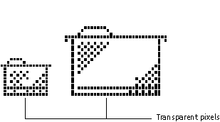
7. Define the empty area around the icon graphic (in which you have not drawn anything) as transparent pixels in the GIF file. This practice ensures that the background color shows through; if the icon is dragged to or displayed on a different background, the area surrounding it matches the color or pattern of the rest of the background. | |


CREATING BACKGROUND IMAGES
HOW TO CREATE A TRANSPARENT BACKGROUND IMAGE (TBI)
AQUIRE THE INITIAL IMAGE:
First get a 256 color or grayscale image by what ever means you are familiar with. 0n-line archive, clipart, graphics packages, or draw it using any of a number of drawing tools.Another technique using MS Windows, is the Print Screen key on most keyboards, which copies the on screen image into clipboard.You can then paste and edit the image into the software of your choice.
ISOLATE THE BACKGROUND:
It is very important that the color you choose for the background or whatever effect you are creating is not used elsewhere in the image, because that color is going to be defined as transparent.
Also, a solid color is preferred if you want total transparency.
MAKING THE BACKGROUND TRANSPARENT:
Load the image into Lview Pro 1.B File/Open
Choose Options/Background color... . If you want a interlaced image, make sure you have the Save GIFs interlaced option checked.
You will get a Select Color Palette Entry window displaying a number of square colored palettes. I prefer to have the area that is not going to become transparent, masked in black. Therefore make sure there is an X in the Mask selection using: box and the Black buttonis on.
Now pick the colored box in the Select Color Palette Entry area that matches the color you want to make transparent. You should now see your image as two colors. The choosen color and the black (masked) area. Then select OK
Now you must save your image. File/Save or File/Save as... can be used. An HTML background is simply an image that is repeatedly displayed in the browser window "behind" the text and foreground images. You load a background image using the <BODY> tag. For example, to load a background image named SLATE.GIF, you'd enter this: <BODY BACKGROUND="SLATE.GIF"> It's also a good idea to set BGCOLOR to a color that matches the dominant color of your background image, like this: <BODY BACKGROUND="SLATE.GIF" BGCOLOR="GRAY"> CONVERT TO SEAMLESS PATTERN METHOD One of the easiest ways to create a background image using Paint Shop Pro is to make a selection and then use Selections > Convert to Seamless Pattern after painting an empty new image with a single color using one of PSP's textures. Here's an example: With a tannish-yellow as the Background color and a brownish color as the Foreground color, open a new 200x200 image. Pick the Flood Fill tool. On the Color Palette, set the Foreground Style to Solid Color and set the Foreground Texture on. Choose the Woodgrain texture. Fill the image with the Foreground color by clicking inside the image canvas. Pick the selection tool, then select an area of your woodgrained image. Select an area that you find pleasing and that is not too close to the edge of your image. Choose Selections > Convert to Seamless Pattern. If Convert to Seamless Pattern is grayed out, check to see if you have made a selection. If Convert to Seamless Pattern is available but you get an error message that the selection is too close to the image's edge, then go back and try selecting an area that is further from the edges. With a little adjusting, some of these might be tweaked into acceptability. And with a lot of fiddling, all of them could be made into nice backgrounds. For images that have fuzzy edges or "noisy" patterns, this method actually works quite well. A concrete-like pattern can be made this way: Open a 200x200 image with Background color set to White and Image type set to Greyscale. Select Effects > Noise > Add. Select Random and set the amount of noise to 50% or so. Select Effects > Blur > Blur, followed by Effects > Texture Effects > Emboss. If you think the brightness or contrast needs adjusting, use Colors > Adjust > Brightness/Contrast or one of the other methods available under Colors > Adjust. Follow the directions given above for using Convert to Seamless Pattern. The result will look something like this: Open the image from which you want to create the tile. Crop it if necessary to get the basic tile that you want. YOU THEN REFINE THE EDGES IN A FEW NOT-SO-EASY STEPS: Select All and then copy the selection to the clipboard. Increase the canvas size to twice the height and twice the width of the original image. (Select Image > Canvas Size and then set the height and width appropriately. Be sure that Center image vertically and Center image horizontally are not selected.) Paste the selection from the clipboard below the original image, being careful to match the edges as closely as possible. Use the Retouch tool or Clone brush (or, if you're really compulsive, the Paintbrush) to "blend" the edges together. Be sure to note the vertical position where the two copies of the image meet, too, so that you can crop out the extra copy later on. Paste the selection from the clipboard to the right of the original image, then blend the edges of the right copy and the original as you did in the last step with the bottom copy and the original. Be sure to note the horizontal position where the original and the right copy meet, so that you can crop out the extra copy. Now the really hard part: Select the blended right edge (from several pixels to the left of the edge to the very edge itself) and copy this selection to the clipboard. Then paste that copy as a new selection and place it on the left edge of the original image area, being careful to position the selection exactly. Do the same thing with the bottom edge, starting your selection a few pixels up from the edge and going to the exact bottom edge. Copy that selection to the clipboard, then paste the copy as a new selection and place it exactly over the top edge of the original image. Select the area of the original image, using the vertical and horizontal positions you noted earlier as guides. Use Image > Crop to Selection to crop away the extra copies that you pasted in in the previous steps. HANDMADE SEAMLESS PATTERNS II: And here's a much easier way to make a handmade seamless tile by hand! First, get a plugin filter such as Sandy Blair's Half Wrap, available on his Simple Filters page. (If you're not sure how to install plugin filters for Paint Shop Pro, follow the directions Sandy gives.) Apply the filter to the image you want to use as your tile. (It's safest to use a copy of the image rather than the original, of course!). Here's an example of an unfiltered image and the result of applying Half Wrap:
Use the Retouch tool or Clone Brush to "hide" the image's original edges, which are now inside the image. Be careful not to alter the new outside edges.
Save the finished tile as a GIF or JPEG. Here's my finished tile: You can click on this tile to see how it would look on a page. The easiest and most effective way to make a seamless background tile is to use a plug-in filter specifically designed for this purpose, such as some of Sandy Blair's other Simple Filters. Below are some examples of tiles I made using these filters, following the result in each case with a hot wax coating (Effects > Artistic Effects > Hot Wax Coating):
You can click on any of these tiles (even the original) to see how they would look on a page. You might also want to take a look at the Effects section for a brief discussion of plugin filters. And check the How To page for tutorials on creating seamless tiles using PSP's Pattern and Rotating Mirror Effects. | ||||||


COLOR MODELS:
A color model or colour model is an abstract mathematical model describing the way colors can be represented as tuples of numbers, typically as three or four values or color components. When this model is associated with a precise description of how the components are to be interpreted (viewing conditions, etc.), the resulting set of colors is called a color space. This section describes ways in which human color vision can be modeled.
RGB COLOR MODEL:
Media that transmit light (such as television) use additive color mixing with primary colors of red, green, and blue, each of which stimulates one of the three types of the eye's color receptors with as little stimulation as possible of the other two. This is called "RGB" color space—see also RGB color model. Mixtures of light of these primary colors cover a large part of the human color space and thus produce a large part of human color experiences. This is why color television sets or color computer monitors need only produce mixtures of red, green and blue light. See Additive color.
Other primary colors could in principle be used, but with red, green and blue the largest portion of the human color space can be captured. Unfortunately there is no exact consensus as to what loci in the chromaticity diagram the red, green, and blue colors should have, so the same RGB values can give rise to slightly different colors on different screens.
CMYK COLOR MODEL:
It is possible to achieve a large incorrect range of colors seen by humans by combining cyan, magenta, and yellow transparent dyes/inks on a white substrate. These are the subtractive primary colors. Often a fourth black is added to improve reproduction of some dark colors. This is called "CMY" or "CMYK" color space.
The cyan ink will reflect all but the red light, the yellow ink will reflect all but the blue light and the magenta ink will reflect all but the green light. This is because cyan light is an equal mixture of green and blue, yellow is an equal mixture of red and green, and magenta light is an equal mixture of red and blue.
HUE, SATURATION, AND VALUE COLOR MODEL:
The HSV (Hue, Saturation, and Value) color model is more intuitive than the RGB color model. The user specifies a color (hue) and then adds white or black. There are 3 color parameters: Hue, Saturation, and Value. Changing the saturation parameter corresponds to adding or subtracting white and changing the value parameter corresponds to adding or subtracting black.
The 3D representation of the HSV model is derived from the RGB mode cube. If we look at the RGB cube along the gray diagonal we can see a hexagon that is the HSV hexcone. The hue is given by the angle about the vertical axis with red at 0°, yellow at 60°, green at 120°, cyan at 180°, blue at 240°, and magenta at 300°. Note that the complementary colors are 180° apart.

The saturation varies between 0.0 <= s <=1.0 and is the ratio of purity of a related hue to its maximum purity at s="1." at s equals 0 is the gray scale, that is the diagonal of the RGB cube corresponds to v of the HSV hexcone. notice the complementary colors( red + cyan, blue + yellow, green + magenta ) are diagonally opposite.So to choose a color we do the following:
1. select pure hue (specifies H and sets S = V = 1)
To add black decrease V and/or to add white decrease S.
For Example: pure blue H = 240°, S = V = 1
dark blue H = 240°, S = 1, V = 0.40
light blue H = 240°, S = .3, V = 1.0
INTUITIVE COLOR CONCEPTS:
Artists start with a "pure color or hue", then add black pigment to produce different shades. The more black pigment the darker the shade. They add white pigment and get different tints. Adding both black and white pigments gives different tones. If we look at the cross-section of the hexcone we can see the analogy with the artists model.

The human eye can distinguish about 128 different hues, 130 different tints (saturation levels), and from 16 (blue part of spectrum) to 23 (yellow part of spectrum) different shades. So we can distinguish about 128 X 130 X 23 = 380,000 colors.
COLOR DEPTH:
Color depth is a computer graphics term describing the number of bits used to represent the color of a single pixel in a bitmapped image or video frame buffer. This concept is also known as bits per pixel (bpp), particularly when specified along with the number of bits used. Higher color depth gives a broader range of distinct colors.
INDEXED COLOR
A 2-bit indexed-color image. The color of each pixel is represented by a number; each number corresponds to a color in the palette.
With relatively low color depth, the stored value is typically an index into a color map or palette. The colors available in the palette itself may be fixed by the hardware or modifiable. Modifiable palettes are sometimes referred to as pseudocolor palettes.
1-bit color (21 = 2 colors) monochrome, often black and white
2-bit color (2² = 4 colors) CGA, gray-scale early NeXTstation
3-bit color (2³ = 8 colors) Many early home computers with TV out displays
4-bit color (24 = 16 colors) as used by EGA and by the least common denominator VGA standard at higher resolution
5-bit color (25 = 32 colors) Original Amiga chipset
6-bit color (26 = 64 colors) Original Amiga chipset
8-bit color (28 = 256 colors) Most early color Unix workstations, VGA at low resolution, Super VGA, AGA
12-bit color (212 = 4096 colors) some Silicon Graphics systems, Color NeXTstation systems, and Amiga systems in HAM mode.

Old graphics chips, particularly those used in home computers and video game consoles, often feature an additional level of palette mapping in order to increase the maximum number of simultaneously displayed colors. For example, in the ZX Spectrum, the picture is stored in a two-color format, but these two colors can be separately defined for each rectangular block of 8x8 pixels.
As the number of bits increases, the number of possible colors becomes impractically large for a color map (a 20 bit depth would require more memory to store the colormap than is required to store the pixels themselves). So in higher color depths, the color value typically directly encodes relative brightnesses of red, green, and blue to specify a color in the RGB color model.
8-BIT DIRECT COLOR:
A very limited but true direct color system, there are 3 bits (8 possible levels) for both the R and G components, and the two remaining bits in the byte pixel to the B component (four levels), enabling 256 (8 × 8 × 4) different colors. The normal human eye is less sensitive to the blue component than to the red or green, so it is assigned one bit less than the others. Used, at least, in the MSX2 system series of computers in the early 1990's.
Do not confuse with an indexed color depth of 8bpp (although it can be simulated in such systems selecting the adequate table).
12-BIT DIRECT COLOR:
In 12-bit direct color, there are 4 bits (16 possible levels) for each of the R, G, and B components, enabling 4,096 (16 × 16 × 16) different colors. This color depth is sometimes used in devices with a color display, such as mobile telephones and other equipment.
HIGHCOLOR:
Highcolor or HiColor is considered sufficient to provide life-like colors, and is encoded using either 15 or 16 bits:
15-bit uses 5 bits to represent red, 5 for green, and 5 for blue. Since 25 is 32 there are 32 levels of each color which can therefore be combined to give a total of 32,768 (32 × 32 × 32) mixed colors .
16-bit color uses 5 bits to represent red, 5 bits to represent blue, but (since the human eye is more sensitive to the color green) uses 6 bits to represent 64 levels of green. These can therefore be combined to give 65,536 (32 × 64 × 32) mixed colors. Sixteen-bit color is referred to as "thousands of colors" on Macintosh systems.
LCD DISPLAYS:
Some modern LCD displays use dithered 18-bit color (64 × 64 × 64 = 262,144 combinations) to achieve faster transition times, without sacrificing truecolor display levels entirely.
TRUECOLOR:
Truecolor can frequently mimic many colors found in the real world, producing 16.7 million distinct colors. This approaches the level at which the human eye can distinguish colors for most photographic images, though image manipulation, some black-and-white images (which are restricted to 256 levels with Truecolor) or "pure" generated images may reveal the limitations.
24-bit Truecolor uses 8 bits to represent red, 8 bits to represent blue and 8 bits to represent green. 28 = 256 levels of each of these three colors can therefore be combined to give a total of 16,777,216 mixed colors (256 × 256 × 256). Twenty-four-bit color is referred to as "millions of colors" on Macintosh systems.
32-BIT COLOR:
"32-bit color" is a misnomer when regarding display color depth. A common misconception is that 32-bit color produces 4,294,967,296 distinct colors.
In reality, 32-bit color actually refers to 24-bit color (Truecolor) with an additional 8 bits, either as empty padding space or to represent an alpha channel. Considering red, green, and blue use the same amount of bits for their respective color (with the exception of 16-bit color), the total bits used will be a multiple of 3: like 15-bit color (5 bits each) and 24-bit color (8 bits each). The reason for using empty space is that all but the newest modern computers process data internally in units of 32 bits; as such, using this amount for each pixel can allow speed optimizations, albeit increasing the required video memory.
BEYOND TRUECOLOR:
In the late 1990s, some high-end graphics hardware and scanners, such as from SGI, started to use more than 8 bits per channel, such as 12 or 16. This has never become common, as the gain in color resolution is almost invisible – 10 bits per channel seem to be enough to reach the absolute limits of human vision under almost all circumstances.
However, professional-quality image manipulation software has started to employ 16 bits per color channel for internal storage, providing protection against accumulating rounding errors when multiple consecutive manipulations are performed on a picture.
For extended dynamic range imaging, including high dynamic range imaging (HDRI), floating point numbers describe numbers in excess of 'full' white and black. This allows an image to describe accurately the intensity of the sun and deep shadows in the same colour space. Various models describe these ranges, many employing 32 bit accuracy per channel. A new format is the ILM "half" using 16-bit floating point numbers, it appears this is a much better use of 16 bits than using 16-bit integers and is likely to replace it entirely as hardware becomes fast enough to support it.
TELEVISION COLOR:
Most of today's TVs and computer screens form images by varying the intensity of just three primary colors: red, green, and blue. Bright yellow, for example, is composed of equal parts red and green, with no blue component.
However, this is only an approximation, and is not as saturated as actual yellow light.For this reason, recent technologies such as, Texas Instruments's BrilliantColor augment the typical red, green, and blue channels with up to three others: cyan, magenta and yellow. Mitsubishi and Samsung, among others, use this technology in some TV sets. Assuming that 8 bits are used per color, such six-color images would have a color depth of 48 bits.
The ATI FireGL V7350 graphics card supports 40-bit and 64-bit color.
COLOR CALIBRATION:
This article is about the color calibration of output devices such as displays and printers.
The aim of Color calibration is to adjust the colors of one output device to match that of another. The device that is to be calibrated is commonly known as calibration source; the device that serves as a comparison standard is commonly known as calibration target. Both target and source can be a Color space such as Adobe RGB or CMYK color space, a test print, color chart or material sample.
INFORMATION FLOW AND OUTPUT DISTORTION:
A computer program that sends a signal to the computer's graphic card in the form RGB (Red,Green,Blue) 255,0,0, signals only a device instruction, not a color itself. This instruction then causes the connected display to show Red to the maximum achievable brightness, while the Green and Blue components of the display remain dark. The resultant color being displayed, however, depends on two main factors:
The phosphors or crystals actually producing a light that falls inside the red spectrum and
the overall brightness of the color resulting in the desired color perception. (An extremely bright light source will always be seen as white, irrespective of spectral composition.)
Hence every output device will have its unique color signature, displaying a certain color according to manufacturing tolerances and material deterioration through use and age. If the output device is a printer, additional distorting factors are the qualities of a particular batch of paper and ink.
The conductive qualities and standards-compliance of connecting cables, circuitry and equipment can also alter the electrical signal at any stage in the signal flow. (A partially inserted VGA connector can result in a monochrome display, for example, as some pins are not connected.)
COLOR PERCEPTION:
Color perception is subject to ambient light levels, and the ambient white point. (A red object looks black in blue light.) It is therefore not possible to achieve calibration that will be perceived evenly in different lighting conditions. The computer display and calibration target will have to be considered in controlled, predefined lighting conditions. Controlled lighting conditions such as D65 help to suppress the effect of metameric colors which would further complicate the issue.
TECHNIQUES AND PROCEDURES:
The most common form of calibration aims at adjusting monitors and printers for photographic reproduction. The aim is that a printed copy of a photograph appears identical in saturation and dynamic range to the source file on a computer display. This means that two independent calibrations need to be performed:
The computer display needs to represent the colors of the image color space.
The printer needs to match the computer display.
In the first stage, an external calibration device is attached flat to the display's surface, shielded from all ambient light. The calibration software sends a series of color signals to the display and compares the values that were actually sent against the readings from the calibration device. This establishes the current offsets in color display.
Depending on the calibration software and type of monitor used, the software either creates a correction matrix (i.e. an ICC Profile) for color values before being sent to the display, or gives instructions for altering the display's brightness/contrast and RGB values through the OSD. This tunes the display to reproduce parts of a desired color space. (It is technically and procedurally not possible to reproduce an exact color space on a computer display). The calibration target for this kind of calibration is that of print stock paper D65 at 120 cd/m2.
In the second stage, the software sends a test print to the printer and compares the print result with the original file with the use of an external calibration device, similar to the display calibration. A calibration profile is necessary for each printer/paper combination.
CALIBRATION DEVICES:
Several devices available for calibrating display monitors are listed here:
Huey, from Pantone is a low-cost, easy to use unit.
Xrite Eye One Display
ColorVision Spyder2 Suite Color Calibration System
Pantone Eye-One Display 2 Colorimeter
ColorVision Spyder2Express professional but easy to use and affordable.
How to create Gradient type in Illustrator:
Gradients can create great looking effects when used right. | |
| |
| Select a thin font from the Character palette or from the Type menu, then select the Type tool ( |
| |
| Create a gradient of your choice in the gradient palette. You can see the gradient I used below. Select the Gradient tool (
|
| |
| Now we will make a duplicate of our type right behind it. To do this, first copy the type to the clipboard by pressing Ctrl+C, then press Ctrl+B to paste it in back. Now, we will expand our newly created duplicate a little bit by using Object > Path > Offset Path. I used an offset of 2 points, and set the joins round. You may try different settings as you see fit. |
| |
| You don't really need to do this, but since we are on a white background for the time being, the real effect we are after may not look very good unless we create an outline around our type. First use the Unite icon in the PathFinder palette to make the now expanded duplicate a uniform object (if you don't do this, you may get unexpected results when you stroke it). Set the stroke color black (or a dark color), and the stroke width 1 point (or bigger - your choice). |
| |
| In a moment, our type will come in focus. Select the Gradient tool again, and fill the duplicate with the same gradient. But this time, use a different direction and/or distance. Voila, that's it! |
| Now the effect is complete, but to make it more dramatic, you may add a dark color background (see left), or apply a drop shadow. In short, just experiment a little bit! |


OIL PAINTING –
Is the process of painting with pigments that bound with medium of drying oil — especially in early modern Europe, linseed oil. Often an oil, such as linseed was boiled with a resin such as pine resin or even frankincense, these were called 'varnishes' and were prized for their body and gloss. Other oils occasionally used include poppyseed oil, walnut oil, and safflower oil. These oils give various properties to the oil paint, such as less yellowing or different drying times. Certain differences are also visible in the sheen of the paints depending on the oil. Painters often use different oils in the same painting depending on specific pigments and effects desired.
OVERPAINTING-
By definition must be done over some type of underpainting, in a system of working in layers. If the underpainting is like a base rhythm in music, then the overpainting is like the solo. The underpainting gives a context in which the paint-strokes of the overpainting become more resonant and powerful. When properly done, overpainting does not need to completely obscure the underpainting. It is precisely the interaction of the two that gives the most interesting effects.Overpainting was used extensively in many schools of art. Some of the most spectacular results can be seen in the work of Jan van Eyck.
It can be difficult to distinguish overpainting from underpainting in finished historical artworks in the absence of scientific tests. X-rays are often used to examine paintings because they allow the conservation technician to see what is hidden underneath a surface without having to damage it. By using different intensities of x-rays, experts can see different layers of paint and therefore know whether or not a canvas was ever painted over.
UNDERPAINTING-
Gets its name because it is painting that is intended to be painted over (see overpainting) in a system of working in layers. There is a popular misconception that underpainting should be monochromatic, perhaps in gray-scales. In fact, a multi-color underpainting is much more useful and was used extensively by artists such as Giotto (whose techinque is described in detail by Cennino Cennini), as well as by Jan van Eyck and Roger van der Weyden (whose technique has been studied with modern scientific analysis). The colors of the underpainting can be optically mingled with the subsequent overpainting, without the danger of the colors physically blending and becoming muddy. If underpainting is done properly, it facilitates overpainting. If it seems that if one has to fight to obscure the underpainting, it is a sign that it was not done properly.


.jpg)


0 comments:
Post a Comment